Nickel-Iron battery specifications
⚠️ Heads-Up: Read Before Commissioning
Dear customer,
Thank you for choosing Nickel-Iron batteries. Ni-Fe batteries are extremely robust and long-lasting. Regular, scrupulous maintenance will ensure their long service life. Please read this documentation carefully before commissioning your batteries.
Important notices
- This documentation contains important information on the Nickel Iron battery specifications. Failure to comply with the following instructions may have serious consequences for battery performance and service life.
- PERMA-BATTERIES reserves the right to modify the content of this documentation at any time.
- PERMA-BATTERIES is not responsible for any errors that may be contained in this documentation.
- PERMA-BATTERIES is not liable for direct damages arising from the use of this documentation.
- Please keep this documentation readily available for anyone who needs to work on the batteries.
I. Nickel-Iron battery specifications :
Nickel-iron batteries have a so-called “pocket-plate” design, where the reagents used for the electrodes are encapsulated in powder form in thin micro-perforated plates, then assembled together to obtain the desired capacity. This page summarizes the most important Nickel Iron battery specifications for design, operation, and maintenance.
The “positive” plate contains nickel hydroxide (NiOH), while the “negative” plate contains iron oxide (FeOH). The design remains faithful to Thomas Edison’s original 1901 patent. The electrolyte is an aqueous solution of potash (KOH) at around 20% by volume, and lithium at around 5% by volume.
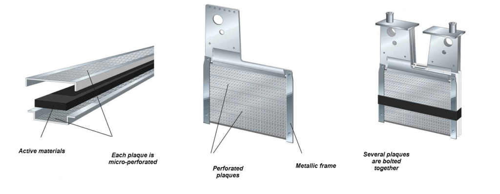
This type of design offers superior mechanical strength and excellent robustness of the internal components. The exceptional longevity of NiFe batteries can be explained chemically. Structural degradation of the components (iron and nickel electrodes) is prevented by an alkaline electrolyte that does not attack metals, ensuring decades of long life and robust operation. These characteristics are core to practical Nickel Iron battery specifications for stationary storage.
Electrochemical reactions can be summarized in the following equation:

(discharge is read from left to right, recharge from right to left)
Furthermore, the operation of an alkaline battery such as a nickel-iron battery relies on an electrolyte that does not recombine with the reactants during cycling, unlike lead-acid batteries (PbSO4 & H2SO4). The chemical role of the electrolyte in a Ni-Fe battery is solely to enable ionic conductivity between the cells through OH- exchange. As a result, the density of the electrolyte in a Nickel-Iron battery remains unchanged, and the risk of stratification due to partial states of charge is eliminated, enabling subsequent capacity additions.
A.Nickel Iron battery specifications : capacity and voltage evolution
The capacity of a Ni-Fe battery is expressed in Ah (ampere-hours), at 20°C +/- 5° C, and corresponds to the amount of energy recoverable under a 0.2 ItA charge for 5 hours (i.e. a discharge current of C/5), after having been ế fully charged for 8 hours at 0.2 ItA.
The open circuit voltage (OCV) of a fully charged Nickel-Iron cell is between 1.3 and 1.5V (typical value 1.45V per cell). This value depends not only on the time elapsed after reaching full charge (self-discharge rate), but also on other variables such as temperature, discharge current, and the cell’s internal resistance.
The nominal voltage (vEMF) of a Nickel-Iron cell corresponds to the potential difference between the electrodes, and is approximately 1.2 V per cell. Consequently, the nominal voltage of a Ni-Fe battery bank will be N × 1.2 V (where N represents the number of cells). When comparing systems, Nickel Iron battery specifications typically cite both nominal (1.2 V/cell) and recommended charge voltages (see MPPT section).
The capacity of a Ni-Fe cell varies according to the discharge current used. The higher the discharge current, the lower the actual capacity.
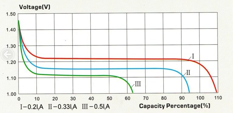
Although Ni-Fe is capable of withstanding peak discharge currents of up to C/4, given its intrinsically high internal resistance (low solubility of Fe & Ni electrodes), optimum performance will be obtained with slow discharges (C/15 to C/20), which is compatible with stationary applications where sustained inrush currents are rare (isolated sites, or hybrid applications).
B. Internal resistance and temperature impact
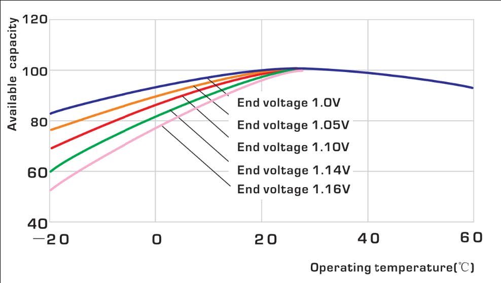
The internal resistance of a Ni-Fe battery depends not only on its state of charge (SOC), but also on the ambient temperature. Compared with the internal resistance of a fully charged Ni-Fe cell at 20°, internal resistance will be 20% higher at 50% SOC (when the battery is half empty). When the battery is 90% discharged, internal resistance will be 80% higher than when fully charged. Temperature also has a major impact on resistance. Below 0°, internal resistance will be 40% higher than at room temperature. These criteria therefore need to be taken into account for high inrush currents, which would cause a drop in battery voltage leading the inverter to disconnect, but having no consequences for either the batteries or the inverter.
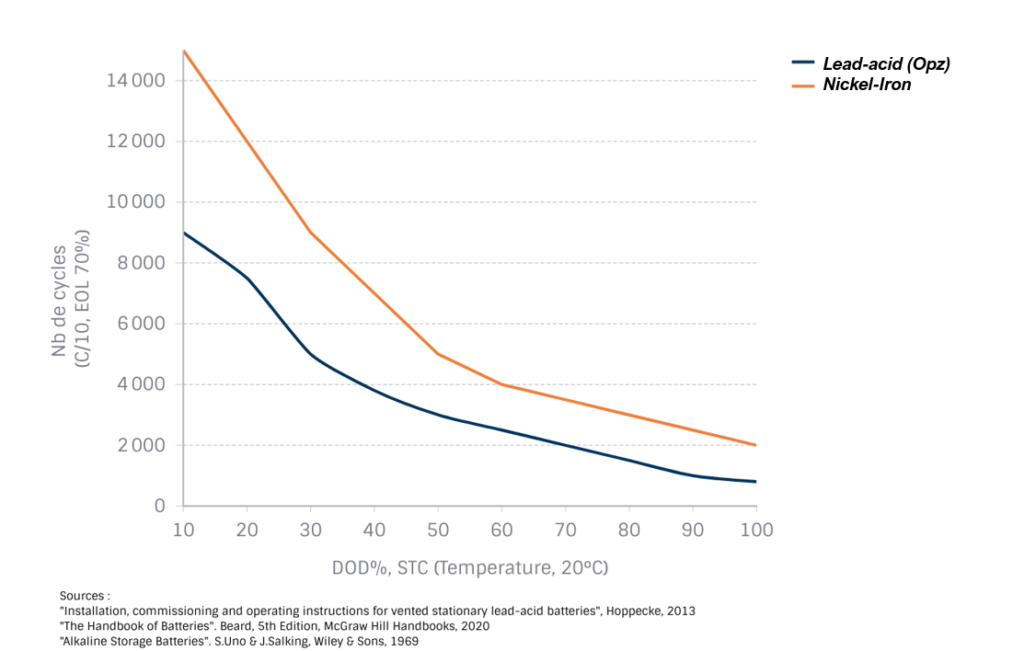
C. Cycle life and endurance
The regular cycling endurance of a Ni-Fe battery is very high, enabling it to achieve excellent cyclic endurance at medium DODs. The absence of sudden-death phenomena due to the very low solubility of the elements means that operating times of several decades can be achieved at different EOLs (end-of-life).
D. Operational parameters :
⚙️ MPPT Setup for Nickel-Iron — Key Takeaways
- Use “Custom Battery” type: Most MPPTs default to lead-acid; select Custom and enter Ni-Fe voltages.
- Charging voltages
- Absorption/Bulk: set to 1.65 V per cell; you must reach this in bulk and hold it during absorption.
- Absorption control: base absorption on time, not an end-of-charge current/voltage cutoff.
- Float: set to 1.45 V per cell.
- Commissioning note: gentle electrolyte “bubbling” during run-in is normal.
- Temperature compensation
- Compensation factor:
−3 mV / °C / cell(program this in the MPPT so it adjusts automatically). - Formula:
V(T) = V(25 °C) + (T − 25) × (−0.003 V × cells). - Example (20 cells = 24 V class, Abs = 33.0 V @ 25 °C): at 35 °C → 32.4 V; at 0 °C → 34.5 V.
Most MPPT controllers are designed to use the default settings for a lead-acid battery, but they also feature a “custom” battery type configuration, enabling customized charge voltages to be set for other battery technologies.
You will probably need to use the custom battery type on your charger to configure it correctly for your Nickel-Iron battery bank. The absorption/bulk voltage of Nickel-Iron batteries is 1.65V per cell. You need to reach this voltage during the bulk charge cycle and maintain it during the absorption cycle to charge a Nickel-Iron battery correctly.
The absorption cycle should be based on time, not on an end-of-charge parameter on your charger.
The float voltage of Nickel-Iron batteries is 1.45V per cell.
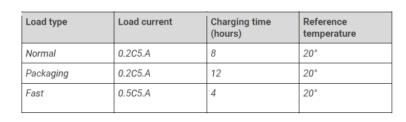
E. Optimal load currents :
The maximum charging currents with an MPPT regulator or a specific charger for a Nickel-Iron battery are as follows :
1.8 Equalizing load
Although not mandatory, an equalization charge every 6 months (or even once a year) helps maintain optimum performance. The equalization procedure consists of a full 10-hour forced charge at 1.65-1.70 per element at C/5, followed by a full discharge at C/5 down to 1.00VDC cut-off voltage.
1.9 Overall yield
The overall efficiency of a Ni-Fe cell depends on several factors, such as charging current, ambient temperature, SOC (state of charge) and internal resistance. The average efficiency of a Ni-Fe battery at 25° is 75% (Wh). Generally speaking, high efficiencies (>80%) are achieved at relatively low SOC levels, and as the battery approaches full charge, efficiencies drop significantly.