Nickel-Iron battery installation guidelines
⚠️ Nickel-Iron Battery Installation Instructions — Read First
Safety notice: Please follow the connection diagrams below. Incorrect connection can lead to short-circuiting and the generation of dangerous currents.
Important installation guidelines
- Verify system voltage & cell count (≈10/20/40 cells for ~12/24/48 V nominal @ 1.2 V/cell).
- Series links must run + → − in sequence. Parallel only identical strings, each with its own fuse/DC breaker before the common bus.
- Confirm polarity at charger/MPPT and inverter before energizing; label positives and negatives clearly.
- Torque interconnects/busbars to manufacturer spec using insulated tools; re-check after first full charge.
- Install a properly rated main DC fuse or breaker as close as practical to the battery positive.
- Use PPE (gloves/eye protection), insulated tools, and remove metallic jewelry during installation.
- Provide ventilation and safe clearances; keep water and neutralizer for accidental KOH contact.
- Only qualified personnel should commission the system; keep these instructions accessible onsite.
I. Nickel-Iron battery installation :
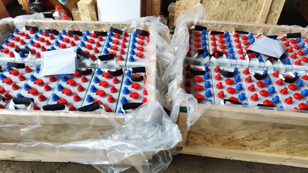
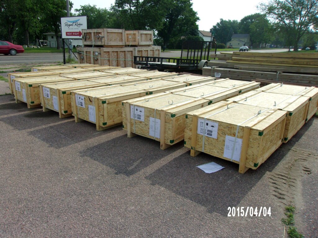
A.Delivery :
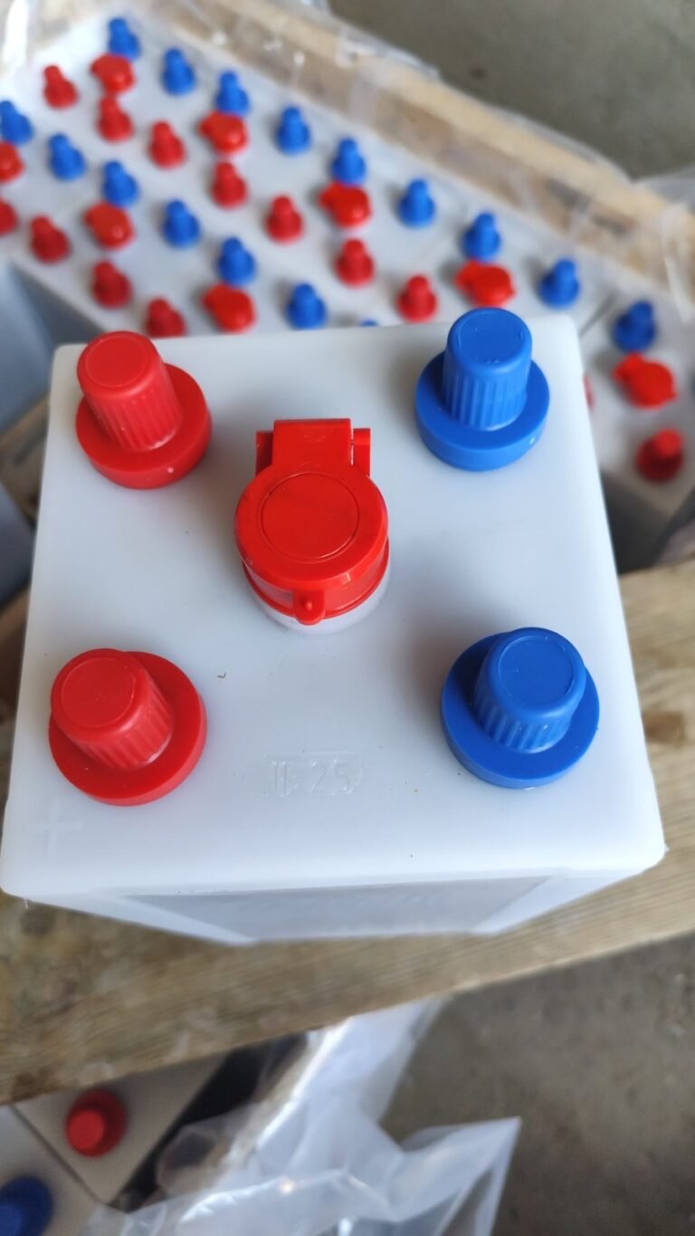
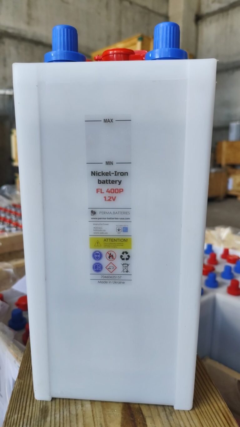
Ni-Fe batteries are supplied pre-filled with electrolyte and do not normally need to be topped up during commissioning, provided that the level is close to the “MAX” line.
Visual inspection of the contents of the shipment must be carried out immediately upon receipt. The customer should take note of any visual indication of electrolyte spillage or leakage. Any evidence of spillage or leakage during shipment must be reported to PERMA-BATTERIES, with supporting photo evidence.
The voltages of each battery should also be measured using a multimeter set to “direct current”. A normal voltage is between ~ 1.2 and 1.3VDC per cell.
NB: the electrolyte level in each cell may vary according to storage time, temperature or other environmental factors. Variable electrolyte levels are not necessarily an indication of leaks or spills. An electrolyte leak or spill will appear as a yellowish liquid or dried electrolyte with crystallized deposits:
B.Installation location and prerequisites :
During the Nickel-Iron battery installation process, you should aim to install them in a dry, clean and safe room. Avoid direct sunlight and heat. The battery will give optimum performance and maximum life if the ambient temperature is between 10°C and 30°C. In addition, the battery room should be sufficiently insulated to limit temperature fluctuations as far as possible.
The site floor must be level and designed to support the weight of the battery system. With larger systems, adequate spacing between rows must be provided to allow access for routine maintenance.
C.Cell connections :
Nickel-Iron battery installation : Safety notice: Please follow the connection diagrams below. Incorrect connection can lead to short-circuiting and the generation of dangerous currents.
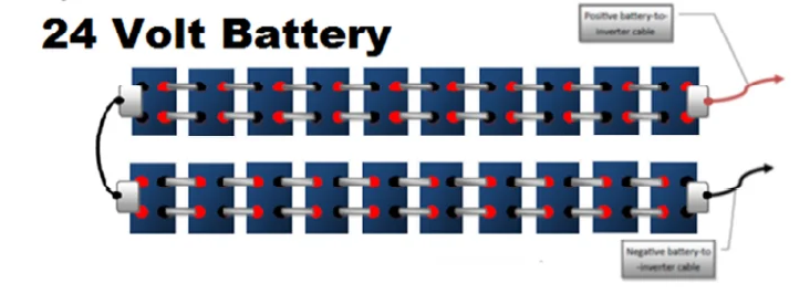
Each Nickel-Iron cell in a park has a nominal voltage of ~ 1.2V. As a result,
– For a 12V park, you need 10x 1.2V elements connected in series (i.e. 1.2×10 = 12V).
– For a 24V park, you need 20x 1.2V elements connected in series (i.e. 1.2×20 = 24V).
– For a 48V park, you need 40x 1.2V elements connected in series (i.e. 1.2×40=48V).
Please follow the connection diagrams below. Incorrect connection can lead to short-circuiting and the generation of dangerous currents.
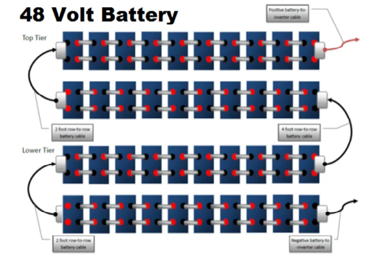
Regarding the layout for the Nickel-Iron battery installation, each battery setup will be provided with 3D plans and sizes. We provide below an example of 3D plans for a set of 48V, 500 Ah NiFe system. Alternatively, for a 48V battery array, you can also choose to have 2 rows instead of 4, as per the diagram below :
Powered By EmbedPress
Depending on the cell’s capacity, it will have 2, 4 or 6 connection lugs of M20 diameter. Each plate is installed in the following order: fit washer – fit connecting plate – fit washer – fit nut – tighten to required torque (5 Nm).
To ensure good electrical conduction and avoid overheating, correct tightening should be carried out using an insulated torque wrench with the appropriate torque.
Once the batteries have been connected, grease the parts in contact with air with mineral oil to prevent corrosion of the metal parts. Before connecting to the inverter, inter-cell junctions should be protected using the insulators provided.
D. Nickel-Iron battery installation : battery conditionning (initial charge)
⚠️ Nickel-Iron Conditioning — Read Before Commissioning
- Running-in is required: full capacity is reached after ~50–100 normal cycles.
- Accelerated conditioning (repeat ≥ 5 times): charge at 0.2C for 12 h to ≈1.65 V/cell, then discharge at C/5 for 5 h down to 1.00 V/cell (0%).
- Constant current only: never use constant-voltage (CV); CV risks thermal runaway (more outgassing → voltage drop → temperature rise → current rise).
- Monitor during conditioning: check cell voltage and temperature regularly; internal cell temperature must stay ≤ 45 °C.
- Worked example (24 V / 300 Ah): charge at 60 A to ≈33 V; discharge at 60 A (~1.44 kW) to 20 V.
- After conditioning: proceed to commissioning and connect to the inverter/charger per installation guidelines.
For compatible constant-current chargers, contact contact@perma-batteries.com or call +1 (415) 818-0845.
Nickel-iron cells require a running-in period, during which their capacity gradually increases until they reach their normal capacity (approximately after 50-100 normal cycles). To speed up this process, we recommend an initial conditioning phase, as follows:
Charge at constant current (DC) with a suitable charger at 0.2C for 12 hours. Then discharge the batteries for 5 hours with a C/5 charge (DC or AC).
Repeat at least 5 times.
For example, a 24V/300Ah battery should be charged for 12 hours at constant current with a current of 300X0.2 = 60A, until a voltage per cell of ~ 1.65V is reached (i.e. 33V for a 24V battery), then discharged with a 60A charge (60A x 24V = 1440W power dissipation) to 0% (1.00V per cell, i.e. 20V for the entire battery).
During the conditioning phase, variables such as cell temperature and cell voltage must be checked regularly. The internal temperature of a Nickel-Iron cell must never exceed 45°C.
A Nickel-Iron battery should never be charged at constant voltage (CV), as this will lead to thermal runaway and damage (increase in outgassing → drop in internal voltage –> increase in temperature → increase in current drawn by the charger). Be sure to use a constant current source.
For a list of compatible chargers, contact Perma-Batteries.
Once the running-in procedure is complete, the Nickel-Iron batteries can be commissioned and connected to the power electronics (inverter-charger).
E. Long-term storage of Nickel-Iron batteries:
📦 Nickel-Iron Storage — Take-Home Points
- Short-term storage (≤ 6 months @ 20–30 °C): no special procedure; keep cells in their original crate or a clean room to limit dust ingress via caps.
- Long-term storage (> 8 months): drain electrolyte and seal filler caps to avoid internal contamination and Iron-electrode passivation; enables multi-decade calendar life.
- Periodic checks: measure individual cell voltages during storage; OCV around ~1.2 V after 6–8 months is common, but the actual charge is effectively zero.
- First connection behavior: expect an initial sharp voltage drop when hooking to the inverter—this is normal and corrected by the running-in/conditioning phase.
- Vacuum / “dry” storage note: plan for a longer initial running-in to chemically recondition electrodes when put back into service.
Next step: run the conditioning (running-in) procedure before commissioning.
Nickel-iron batteries can be stored unused for up to 6 months at room temperature (20-30°C), without any special procedures, other than keeping them either in their original crate, or in a clean room, to limit dust penetration through their caps.
If batteries are to be stored over the long term (more than 8 months), we recommend draining them of their electrolyte, then sealing their filler caps (to prevent internal contamination and avoid passivation of the Iron electrode). This way, they can reach a calendar life of several decades.
On the other hand, you’ll need to measure their individual voltages periodically to monitor their evolution. Normal voltages (~ 1.2VDC) are common after 6-8 months’ storage, but their “real” charge will be zero. Consequently, when they are connected to the solar system’s inverter, it’s normal for the voltage to drop sharply at first, but this will be rectified by the initial running-in phase.
Storing them in a vacuum for a long period will require a longer initial running-in period when they are put into service, in order to chemically recondition the electrodes.
F. Maintenance operations of Nickel-Iron cells :
Maintenance Schedule
| Operation | Frequency | Details / Notes |
|---|---|---|
| Checking electrolyte level | Monthly |
Visual inspection at end of charge; top up only with deionized water if needed. |
| Battery cleaning | Monthly |
Remove dust from terminals and covers; keep surfaces dry and free of debris. |
| Check terminal tightening torque | Annual |
Verify with a torque wrench to manufacturer specification. |
| Lubrication of metal parts | Semi-annual |
Apply mineral grease to terminals and inter-cell junctions (thin protective film). |
| Equalization load |
Semi-annual/Annual
|
Perform per procedure (see Chap. 2 § 1.8). |
| Checking electrolyte density | Every 10–15 years |
Measure with a battery densimeter (see Chap. 3 § 1.3). |
Water refilling
Electrolyte Carbonation — Key Facts
Over time, KOH absorbs CO₂ and forms potassium carbonate (K₂CO₃). This does not damage the cells, but it reduces ionic conductivity and therefore capacity—more noticeable at higher discharge currents.
- Electrolyte refresh: replace entirely every 10–15 years to revive performance.
- Density check: if electrolyte density falls below 1.160 (battery densimeter), replace the solution.
- Performance cue: high discharge currents accentuate capacity loss from carbonation.
Due to the electrolysis of water during recharging, the electrolyte level is consumed gradually, so Nickel-Iron batteries need to be topped up regularly with distilled or deionized water.
Use only deionized water with a TDS below 10 µS/cm
Distilled water should only be topped up at the end of charging, preferably in the evening. During the day, the electrolyte level may fluctuate and not indicate a reliable value. Fill using a funnel or watering gun.
The electrolyte level in each cell should be checked monthly to monitor progress and ensure that the level is above the “MIN” level at all times.
If the electrolyte level is too low, this can cause internal overheating, followed by a thermal runaway that can cause the battery to explode (rupture of the casing) due to the ignition of H2 + 02 gases.
Electrolyte change (reconditionning)
Over the long term, potassium hydroxide (KOH) in the electrolyte of a nickel-iron cell absorbs carbon dioxide (CO²) from the air, recombining in the electrolyte to form potassium carbonate, K²CO3 (carbonation). These carbonate deposits do not damage the cells, but they can lead to a significant reduction in capacity by altering the ionic conductivity of the electrolyte solution. The higher the discharge current, the more pronounced the effect. Although there is no precise consensus on the subject in the technical literature (it is very difficult indeed, given the life span of a Ni-Fe battery, which extends over several decades, to monitor performance with or without electrolyte change), we recommend a total electrolyte change every 10-15 years to revive battery performance.
It is accepted that a carbonate level of up to 80-100g/L for a nickel-iron cell is tolerable.
The KOH concentration of the electrolyte may also decrease significantly over long periods. During recharging, part of the electrolyte is evaporated when the cell is degassed, and a small amount of KOH is lost in this way. In addition, regular topping-up can accentuate this depletion and lower the KOH concentration. One way of measuring electrolyte density is to use a battery densimeter (or acid scale) to check the concentration. When it falls below 1.160, it’s time to change the solution entirely.
⚠️ KOH Handling — Critical Warnings
- DANGER Potassium hydroxide (KOH) is highly corrosive to skin and organic materials.
- Always wear PPE (gloves, eye/face protection, protective clothing) when changing electrolyte.
- Always add KOH into water—never add water into KOH.
Electrolyte composition varies according to the required operating temperature, and breaks down as follows:
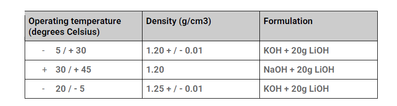
Thus, for a standard density of 1.20g/cm3, one liter of electrolyte will contain :
– ~ 242g KOH (CAS 1310-58-3, min. purity > 90%)
– ~ 950g H2O (distilled / demineralized / ionized water)
– ~ 20g LiOH (CAS 1310-66-3, min. purity > 50%).
The solution prepared in this way cannot be stored (KOH absorbs carbon dioxide from the air). Make sure you use the solution quickly.
The procedure for changing the electrolyte is as follows:
– Fully discharge the cells (0.9V).
– Short-circuit each cell for 3 hours.
– Empty electrolyte into a suitable container
– Rinse the inside of each cell with distilled water. Repeat 2 or 3 times.
– Fill each cell to “MAX” level with the prepared solution.
– Reconnect each cell.
– Perform an equalization load at C/5 for 15 hours.